


















In open-pit mines or layouts where the crushing station is positioned close to the working face, the loading point is not a fixed coordinate. Once the crushing station advances, the muckpile and loading position often must be rearranged, and the excavator may change operating positions several times within a day or a week. This condition differs markedly from "fixed loading position, long-cycle continuous loading": the equipment must provide sufficient operating radius and dump height, be able to relocate itself, travel stably on uneven benches, and withstand repeated heavy-load cycles.
This article addresses a specific question: when loading points move with the crushing station, by which data items should the suitability of a 33-ton tracked excavator be judged, and which parameters can only serve as references and must be verified on site. The article is based on verified data for a 33-ton tracked excavator from this site and does not constitute a conclusion for any specific project.
First, clarify the core conflicts of this operating condition
Moving loading points do not create a single problem but three mutually constraining requirements:
- Working coverage: the relative positions of the loading position, muckpile, and haul trucks change frequently, so the equipment needs to cover a relatively large area without frequent repositioning.
- Relocation efficiency: changing positions means travel, and the tracked undercarriage's gradeability, ground clearance, and wheelbase determine whether it can pass benches and uneven ground.
- Continuous load: advancing the crushing station usually brings concentrated loading tasks, and engine power reserve, hydraulic system pressure, and structural durability affect the stability of continuous operation.
These three requirements are difficult for one machine to fully satisfy at the same time. A large working range usually means a longer boom and larger overall dimensions, while flexible relocation requires a compact undercarriage. Selection is therefore more about trade-offs among several conditions than about finding an absolute optimum.
How working range corresponds to moving loading points
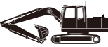
Verified data show that this 33-ton tracked excavator has a maximum digging radius of 10,709 mm, a maximum digging height of 10,491 mm, a maximum dump height of 7,625 mm, and a maximum digging depth of 6,437 mm. In the scenario of moving loading points, dump height and digging radius are the two most direct judgment items.
A dump height of 7,625 mm means there is still some margin to adjust the dumping posture when truck body height and parking position vary. Digging radius relates to whether the equipment can cover different positions of the muckpile from the same stopping position, reducing repeated travel caused by small shifts in the loading point. However, these values are maximums under standard conditions; the actual effective range is affected by boom posture, material stacking height, and ground slope, and cannot be used directly as routine working dimensions.
Another easily overlooked item is the minimum swing radius of 3,643 mm. When space among the crushing station, haul trucks, and muckpile is limited, the sweep range of the rear and counterweight side affects site layout. Moving loading points often mean the equipment must turn within tighter spaces, so this item should be considered together with the site plan.
Travel and relocation conditions cannot rely on grade angle alone
The data give a maximum gradeability of 35°, a minimum ground clearance of 470 mm, a wheelbase of 3,800 mm, and overall dimensions of 11,015 × 3,200 × 3,168 mm. These data support a preliminary judgment: the equipment has some slope-passing capability, and the undercarriage ground clearance leaves margin for gravel and uneven ground.
However, for relocation under moving loading point conditions, what really needs verification is the road condition, not a single angle value:
- Whether the slopes of access roads connecting loading positions are continuous and whether there are sharp curves;
- Whether the road surface is compacted soil, gravel, or soft material piles, and whether 35° occurs only over short local sections;
- Whether track width matches site road width, and whether the 3,200 mm overall width can pass existing passages;
- Relocation frequency and distance, which determine the proportion of travel time in total operating time.
If long-distance frequent relocation is required between loading points, the travel speed and undercarriage wear of tracked equipment will become new constraints. In that case, a more reasonable approach may be to optimize the layout of the crushing station and loading positions rather than relying on the equipment itself to absorb all relocation distance.
Continuous loading depends on engine and hydraulic matching
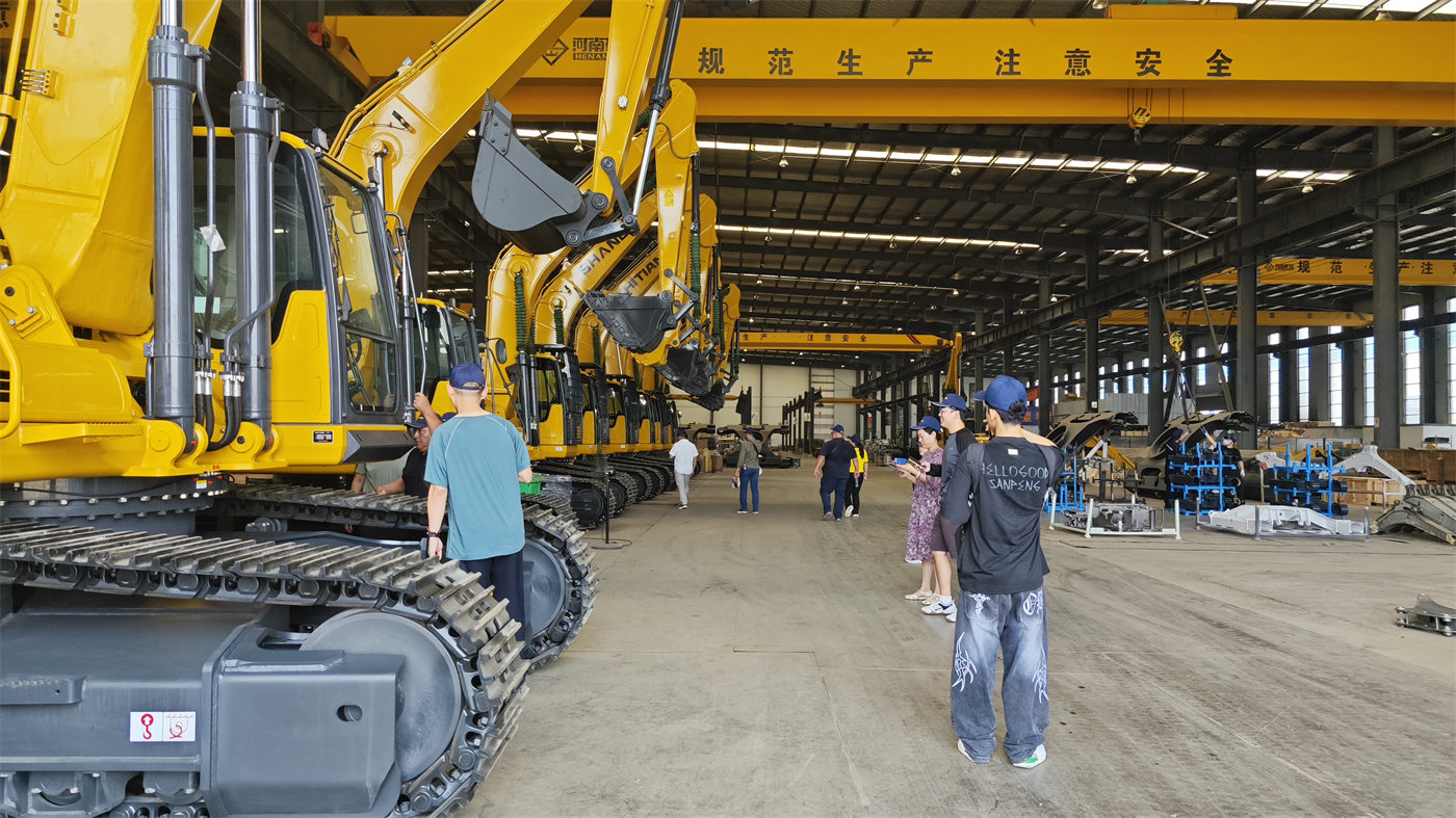
This model is equipped with a 6CTA8.3 engine with a rated power of 194 kW (263.3 hp), a system pressure of 35 MPa, a bucket capacity of 1.6 m³, a maximum bucket digging force of 244 kN, and a maximum arm digging force of 200 kN. For moving loading points, the significance of these values lies in power reserve during high-load cycles and the ability to penetrate the material pile, rather than simply comparing numerical magnitudes.
Loading points moving with the crushing station are often accompanied by uneven muckpile fragmentation and areas that need to be regathered. The 244 kN bucket digging force and 35 MPa system pressure correspond to the ability to maintain penetration and full loading in harder piles. The data also give a swing speed of 0–11 rpm, indicating that the swing link has speed-adjustment capability, making it easier to control the dumping rhythm when truck parking positions are not fixed.
It should be noted that the above are parameters from the overall machine data and do not equal actual loading efficiency under a specific pile or a specific gradation. Material looseness factor, lump size distribution, truck capacity, and parking method will all change the results, and these should be further confirmed by on-site tests or manufacturer technical support.
Structural durability and maintenance conditions
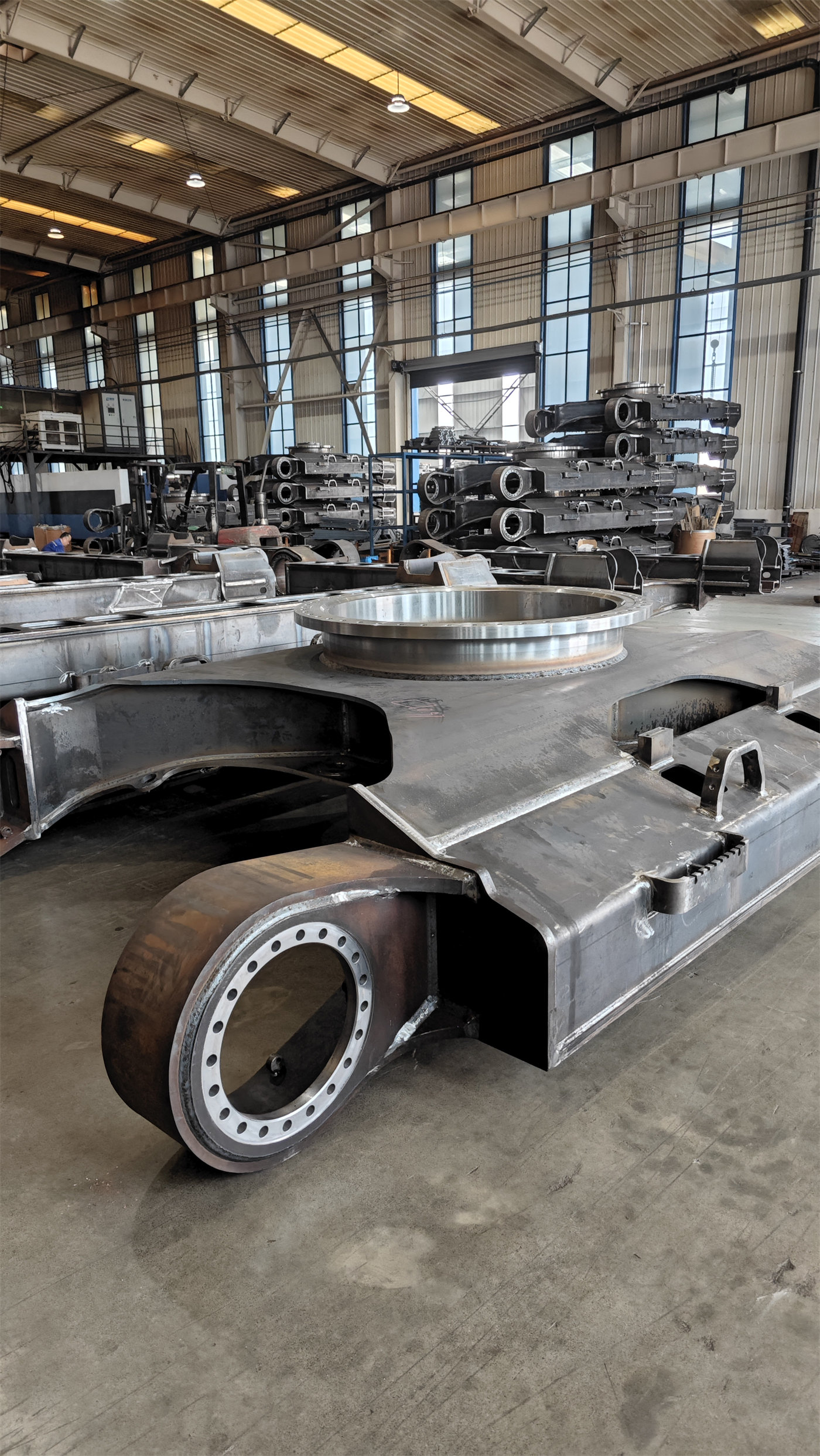
The data mention that this model has been reinforced at key stress points, with the undercarriage and boom using automated welding, and is positioned for high-intensity continuous operation. Moving loading points cause the equipment to switch frequently between travel and heavy loading, and the undercarriage, swing bearing, and boom connection areas experience more pronounced alternating loads. Before mobilization, therefore, the supply of wear parts, inspection points for welded structures, and hydraulic oil cleanliness management should all be included in preparations, rather than focusing only on the specification table.
The data do not give maintenance intervals, failure rates, or overhaul intervals; these should be based on the accompanying documentation and manufacturer service requirements, and this article makes no inferences.

Application boundaries and cases where it should not be directly applied
The data for this 33-ton tracked excavator point to scenarios such as open-pit mining, large-scale earthwork, infrastructure foundations, water conservancy projects, and port cargo handling. For the condition in which loading points move with the crushing station, it is more suitable under the following conditions: changes in loading position are mainly local adjustments on the order of hundreds of meters; road conditions allow tracked travel; and the positions of haul trucks and muckpile fall within the equipment's working range.
If the distance between loading point changes is very long, relocation is extremely frequent, or site passages are so narrow that both overall width and swing radius are constrained, suitability cannot be judged from this data alone and must be separately evaluated in conjunction with the site plan, road longitudinal slopes, and haulage organization. If the project also involves work with attachments such as hydraulic breakers, the attachment is only a supporting condition of the overall machine solution; whether the host has the corresponding hydraulic flow, pressure, return oil, and interface must be checked item by item against the attachment manufacturer's data, and this article does not guarantee that any attachment can be directly installed.
Information to prepare before inquiry and mobilization
To bring the equipment solution to a verifiable level, it is recommended to provide the following at inquiry:
- Layout plan of the crushing station and loading positions, the distance range between them, and relocation frequency;
- Muckpile material type, lump size distribution, and loose stacking height;
- Haul truck model, body height, and parking method;
- Site access road slope, road surface material, passage width, and turning radius;
- Planned daily loading volume, work shifts, and continuous operating duration;
- If attachments are required, provide host hydraulic flow, pressure, return oil conditions, and interface type.
This information determines whether the equipment can cover the working range, whether travel conditions are feasible, and whether continuous load is matched, rather than simply comparing a single value. Site data not given in the materials should be supplemented and confirmed during inspection and trial operation before making the final configuration trade-off.